Week 3
Assignments
-
[ ] Task 1: This project allowed me to meet a need long existent in the lab space, We have a classroom sized set of certain drivers, but having students returning them to a drawer has been a less than effective way of seeing that they are properly stowed, resulting in some of them having gone noticeably missing.
-
[ ] Task 2: The parametric pegboard driver rack.
Process
I’ll be using Adobe Illustrator for finishing up, but I am also taking this opportunity to explore parametric modelling in PTC Onshape.
I start in the physical realm, holding one of the drivers which needs to fit in this rack. I imagine two points of contact in order to hold the driver upright, separated by some distance to maintain the hold. As with any such holder, there is also a goal of maximizing usage of wall space, while minimizing hook attachments.
As a model, I have an existing metal pegboard hook, which I can use for some basic understanding of the way it attaches to the wall. In the variable table, I create a Variable Studio, and add dimensions to it for:
- “materialThick” - the thickness of the material I will be cutting, in this case 3 mm lauan.
- “pegboardHole” - the diameter of each hole in the pegboard pattern, here we have .25 inch holes.
- “pegboardSpace” - the distance from center to center of each pegboard hole, in this case 1 inch.
- “pegboardDepth” - the thickness of the pegboard itself, in this case .25”
Note the mixture of dimensional values here. I am most familiar with Imperial units, but some of my dimensions are more accurate in metric. Onshape doesn’t seem to care, and as long as dimensional units are specified, conversions will be made automatically for the native unit system. As a practice, I have been teaching my students that when a dimension is given in metric, such as the 3 mm lauan, Enter it with the unit given, and let the machine worry about the conversion. It seems to help a little when teaching students to be more fluent in both, as they get comfortable with seeing common values expressed in multiple ways.
Anyway, creating a variable studio is great for dimensions which will be used throughout the project, but Onshape also gives a place for variables local to the part studio being worked within, so I will use that space for the following:
- “hookThick” - the distance from front to back of our part, the “hook” which will need to be less than our pegboard hole in order to fit there, and should be an easy fit. I define this one dynamically, “#pegboardHole-(#pegboardHole-#materialThick)/2” referencing already established dimensions from the Variable Studio, so if any of those change, this value can keep up.
- “gripLength” - the distance of hook which goes into and behind the pegboard to hold the part in place. I chose 3/8 of an inch, following the example of my model hook.
- “backAngle” - the angle the hook bends away from the riser, allowing it to be inserted into the pegboard hole, and hold firm when it arrives there. This also follows the example of my model hook.
- “frontAngle” - the angle the riser bends away from the front of the part, allowing for the space it will be inserted into the pegboard. This also follows the example of my model hook.
- “pegLength” - a secondary insertion into the pegboard, will hold the hook vertical and help lock it in place. This was inspired by the model hook, but I will be adding some locking tabs, as I have noticed the metal version slips out a lot in use, and if I am going to design my own version, why not solve a few issues? This one simply references “pegboardDepth” directly.
- “pegslot” - Part of the novel latching feature, I am borrowing from snap-hooks, and need a slot for the snaphooks to be able to flex into as they are engaged at the wall.
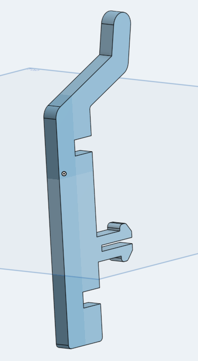
Now to design the hook. I create a sketch using the right plane as the sketch plane. Three rectangles intersect here to make the hook body, using the aforementioned dimensions to “fully constrain” their relationships in space. This is a critical part of parametric modelling, as if there are any features not defined by some relationship or dimension, they can cause interference when values change.
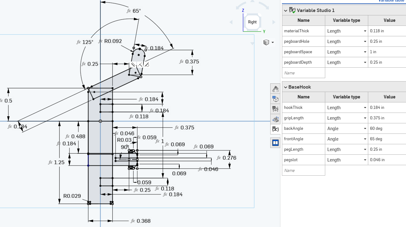
As a practice creating with intentions, I have also designed in some aesthetic or assistive features, using fillets to round off edges which might catch in use. Some dimensions, as a part of the organic process, end up being defined as combinations of established dimensions, and I will recognize here that when teaching with these principles, I have been trying to convince my students that this is not a best practice, as it creates opportunities for things to get confusing later… I will concede that as I teach the philosophy, I am also learning, and am still a somewhat imperfect practitioner.
This sketch is then committed using the green Check button in the sketch pane, and extruded using the tool named for such function.
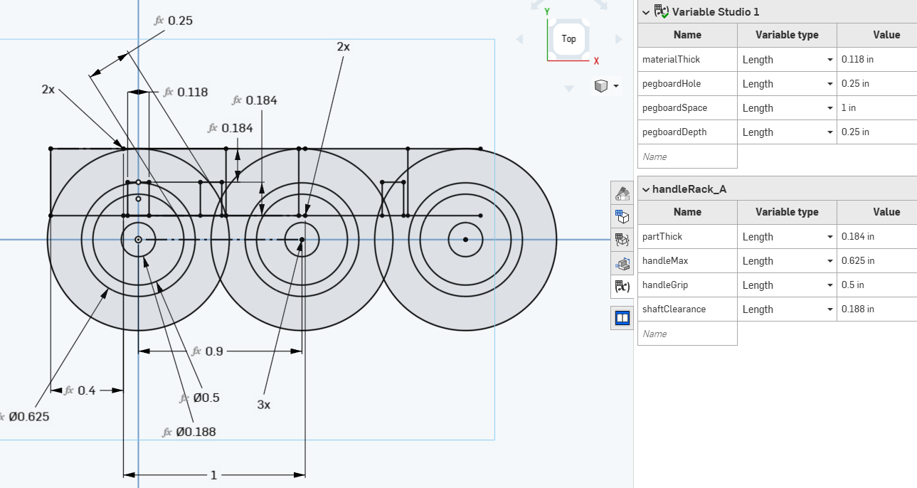
Next, I created a second part studio, called “handleRack” and give its variable table the following dimensions:
- “partThick” - the distance I used before, in defining a relative thickness of my hook-this time it will apply to ensure there is always a minimum amount of material holding features together… I probably could have put this into the Global variable studio, but I didn’t, so I redefine it here: “#pegboardHole-(#pegboardHole-#materialThick)/2”
- “handleMax” - the distance across the whole handle which will rest in this holder. I want them to all fit, so I need to know how close they can rest together without interference.
- “handleGrip” - the distance across the part of the handle which will be held within the holder–should be a feature smaller than handle max, or else the whole thing will fall through, which in this case is why the metal ones were not good enough.
- “shaftClearance” - the distance across the driver shaft, which will be more useful when we get to the lower section of this holder.
This sketch includes features which will end up defining both variations of this part, and when it is done, I make a copy of the part studio, and rename both so that I have a “handleRack_A” and a “handleRack_B” with unique attributes.
Each is extruded, and then I can Insert them into the waiting “Assembly 1” space, to test their fits. I found a pre-existing model in the public library which was a close enough stand-in for my drivers, and it looks like a pretty good fit.
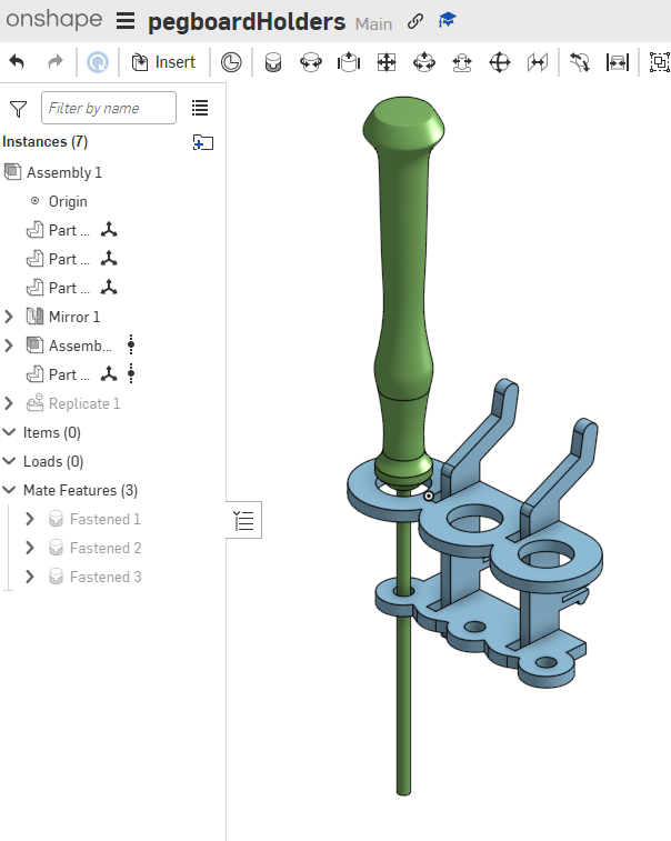
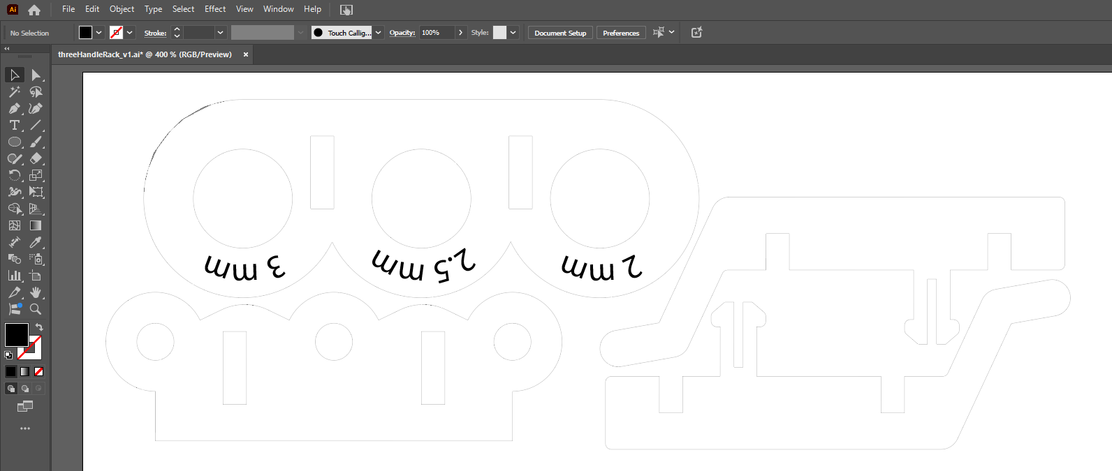
I ended up deciding that holding 3 drivers was more space effective than 1, balanced between 2 hook parts, each of which grip the wall in two places. I exported each of the part-faces as a DXF, and collected them into a common Illustrator file for cutting. In Illustrator, it was much easier to add text for engraving, so I did to create a label for the driver which would be stored in each holder.
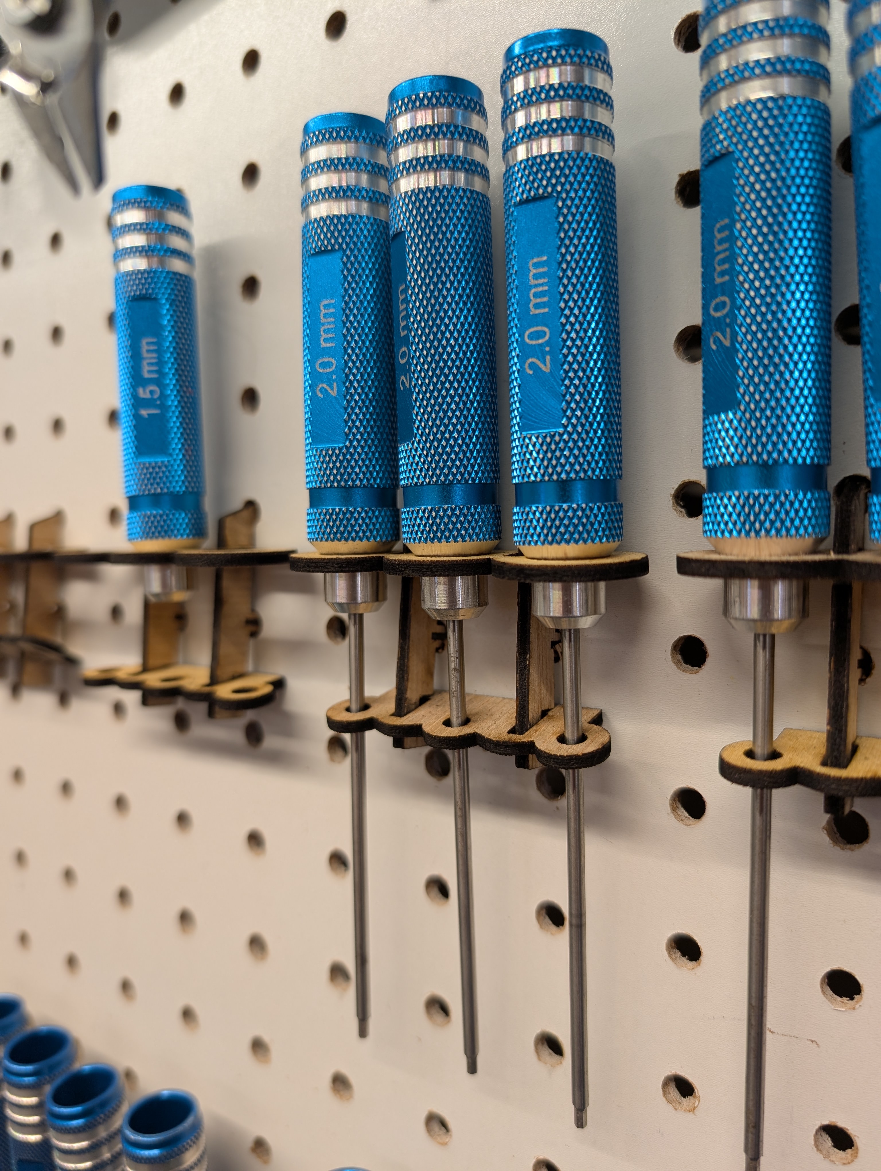
Some of my dimensions did need a little iteration before a perfect fit was achieved, and the resultant assembly feels really flimsy until inserted into the pegboard holes, at which point much of the slop is restricted out, and it becomes a near perfect holder for 3 drivers.
I intend to strip this process down into a much simpler version, and teach it as a basic modeling lesson for my robotics students, letting them each choose a tool for wall-mounting, then problem-solve how to use the given base-hook parts to adapt holders for each tool.
Reflection
Think on one or two educational activities in which you could integrate the laser cutter at some stage of the activity. - Explain briefly the activity. Do not forget to clearly indicate the learning objectives. - For an art class, using the laser to give depth to images created in simple linework. Each element is cut out, and mounted along an edge of a frame which holds it at a unique depth away from the viewer, giving the image a 3 dimensional appeal. Students would learn the distinction between stroke and fill for digitally drawn shapes, and how each impacts a laser cutting file. This lesson would also reinforce ongoing study on principles of art, as students use their laser cut elements to transition between shapes and forms in their finished piece. - Explain briefly the activity. Do not forget to clearly indicate the learning objectives. - A History class uses the laser to create crown shapes toward a lesson on traditional symbols of aristocracy. Students learning about the distinct regal images would get a lesson to incorporate some into a pattern which could be laser cut from simple materials, then rolled into a crown shape and perhaps adorned with other cut elements, or even basic craft supplies to create a unique work which demonstrates understanding and synthesis of unique regal symbols and historical uses.
Reflect on your own practice. - When you prepare a lesson activity what are the things that you take into consideration? - Each lesson should ask the students to consider the information given, in context of previous understanding, and incorporate intention toward direct action based on the novel perspective gained. Each student should have the opportunity to participate in activity which challenges them to incorporate new information into their established understanding. - What are the critical aspects? - Every student should have an active path through the lesson, and that path should include guidance to ensure its completion. In this, consideration should be given to the barriers which will be encountered along the way, both intentionally, based on material, and unintentionally, such as “I forgot my pencil.” While many students arrive with basic supplies for any lesson, there are always a few who are missing something, rendering a critical need to be able to do some gap filling. Additionally, anything the lesson requires beyond the basics of course needs to be present for use as needed, such as worksheets printed, craft supplies at the ready, and presentable materials available in multiple formats to ensure deliverability of the lesson regardless of potential disruptions of classroom technology. In the case of this project, there were several places where a student navigating on their own could have gotten painted into a corner, and indeed, there are a few places where I nearly did myself, only managing to pivot out by making design choices that would have seemed unavailable to someone exploring digital fabrication for the first time. Independent of tech or lesson content, there is a practice to finding project choke-points, and making sure that lesson content can communicate clearly enough to keep things from going to the places where rough-cut solutions are the only way out. - What additional aspects do you need to take into consideration if you utilize digital fabrication processes? - Digital fabrication machinery inevitably runs into bottlenecks where not every student can be issued their own machine to have a singular learning experience with. 3D print jobs often take considerably longer than a class period to complete, and even though laser cuts and CNC operations can happen faster, there are still limits in setting jobs up, which make it impractical for each student to have a unique experience on the machine.
- To counter this, projects which require them get staggered scheduling to ensure as close to the ideal as possible. With laser cutting jobs, students are set up in project sessions which ensure that not everyone reaches readiness for the machine at the same time, then are batched through based on run-time. Projects get constraints which ensure that none of those run-times exceeds a certain threshold, and can be batched as well. For example, students will work at first with paper, felt or cardboard so that parts can be cut quickly.
- Cutting class periods will involve project files that were previously submitted for review, and often the instructor will set up cut files so that each student gets the experience of running the machine, but perhaps only cutting one part, instead of the whole job. The rest of the parts either have been pre-cut, or get batched and cut during a less structured part of the day, so that by the time each student has had their experience cutting a single part, they have everything they need to move on to the next part of the activity.
- 3D prints are often batched this way, with the bulk of the actual printing done outside of class time, While students are constrained to unique elements of specifically small size for in-class prints, then invited to run their own, larger prints in unstructured time before and after school.

- CNC jobs are the hardest, with whole sessions devoted to CAM as a group, then individuals on the machine work in batches with small parts, then invited back to do larger parts during other parts of the day.

- Machine upkeep and material stock are also important considerations, as a preventable maintenance deferral can manifest on production days in ways that derail projects for multiple students in ways that cascade.
Reflect on your past educational activities. - How have you considered Socio-Emotional learning (or soft-skills) when preparing the activities? - One of the most common questions asked by a student is that of, “Is this good?” - Having multiple students creating some element of a lesson, then pausing to ask that, and awaiting the instructor’s remark before taking any other action can create an unintended barrier to progress, so lessons in Digi-fab are often pre-emptively crafted to help students arrive at self-awareness by asking, “What IS good?” and inspecting it among peers, against benchmarks provided in lesson materials. - Could you provide some concrete examples? - In art and computer science classes alike, one project is set up where students are paired into “Client-Creator” relationships, where one student is a client, who is coached along communicating a need to be met by the created project. Each student is creating for another, so everyone gets to understand both sides of the relationship. - As the creator explores creation in the project, they are navigating the needs expressed by the client, and practicing an awareness that goes beyond their own ability to understand whether a goal has been met. - A project which is being created to achieve an academic goal can feel somewhat uncertain, but in the presence of a client who has a specific need to be met, and a way of judging whether or not it has been met, focus can be a little sharper, and the conversations that result allow the students to explore skills in communicating with clarity around those needs. - Even something as simple as “pair programming” can work like this, where the “navigator” carries the understanding of the goal to be met, and practices guiding the “driver” through the accomplishment of that goal. - How have you changed your perspective on socio-emotional learning / soft-skill / horizontal competences after this lecture. - Exploring the ways in which the classroom can simulate real-world scenarios like the client-creator relationship has become even more important, but not just because of the presence of such a dynamic. - I have recognized that I have not yet fully modeled the way this interaction basis can be explored, and hope to use future classes to create scenarios where students use their assignments in my project based classes to create purposeful work that meets needs in the local school community, and creates opportunities for students to have greater agency in project design by becoming their own client, such as creating works to support their passions in other areas of campus, like creating signage for a student club using digifab.
Tools
- Tools or software used
-
- PTC Onshape, Adobe Illustrator, Epilog Helix 50w Laser cutter.